High,medium frequency induction heating quenching furnace engineering design method
2013/1/5 From: Local Views
0 Introduction
High, medium frequency induction heating power supply unit is used for the heat treatment of machine metal parts, widely used in the automobile and other machinery manufacturing industry. The practice shows that the induction heat treatment is the most economical and energy-efficient heat treatment method. Metal heat magazine reported in 1987 of a single heat treatment process energy consumption comprehensive measurement results: in the after 13 energy numerical comparison of the heat treatment process, high frequency induction
The quench energy consumption Low values to 2 to 20 times. In the heat treatment production energy consumption accounted for 80% of the variable costs, the economic effects of energy-efficient induction heat treatment is very significant.

Fast heating induction heat treatment, refinement or ultrafine austenite grains. The induction heating of the part temperature rise rate can reach 200 ° C / s, or even higher, so the austenite grains finer. Meticulous martensite after quenching and then tempering to obtain tempered structure of highly dispersed, is improved due to the strengthening effect of the grain boundary, so that the strength and toughness of the parts.
Induction heating the surface hardening of parts, as hematocrit increases in the martensite in the hardened layer can be formed relatively large residual compressive stress, the maximum value of up to 539 ~ 784MPa, the fatigue strength of its surface compressive stress value of the practice has proved Part significantly correspondence relationship, i.e. pressure large stress, fatigue strength, and improve fatigue life.
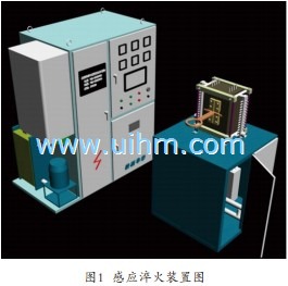
Hardening processing purpose of the induction heating of metal parts is to increase its surface hardness, the principle is: the commercial frequency electrical energy into high-frequency alternating current, and the input coil, inside and around the coil generates an alternating magnetic field, is placed inside the coil metal workpiece is cut by the alternating magnetic field lines of magnetic force, so induced electromotive force E on the ferromagnetic material of the workpiece, and the electromotive force under the action of parts within the eddy current, the maximum surface of the swirl intensity, calculated that by theory, the current penetration depth heat layer accounted for 86.5% of the total eddy current heating. Index curve from the surface to the core section by attenuation, which is the surface layer of the quenching heat treatment process. Figure 1 Figure 2.
1 induction heat treatment process specifications
The induction heat treatment process specification formulation comprising: frequency selection, the heating method and the determination of the heating power, the heating time or continuous quenching of the moving speed of the selection, the cooling medium and the selection of the cooling parameters, etc.. Here mainly to explain the choice of frequency and power.
1) The current choice of frequency
The frequency of the current determines the heating penetration depth, the heating of the workpiece, quenching quality and sensor design. The different frequencies of the current penetration depth in steel is different, the higher the frequency, current penetration depth is shallower, the lower the frequency, the deeper the penetration depth. Specifically with reference to Table 1.
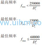
In order to ensure good induction heating surface hardening quality, hardened layer Ds generally less than the diathermy current depth △ 800 ° C, often choose
Cylindrical part surface quenching, the relationship between DS and the frequency f of the hardened layer is available the following formula:
Wherein Ds - hardened layer depth (mm).
In addition, parts diameter hardened layer depth and frequency of the current relationship. Table 3.
2) the power density and the maximum area of the heat quenching
Also known as power density of a specific power, it is an important parameter in the induction heating surface hardening. It represents a unit time to the heating area of the part units, the size of the energy delivery, i.e., kW/cm2. In the same frequency under conditions of the power density of the size determines the speed of the induction heating. In a suitable power density case, the parts can be achieved to the surface heating and rapid heating. It hardened layer forming effect, sometimes over frequency. The physical meaning 1cm2 steel from 20 ℃ was slowly heated to 900 ~ 950 ℃ austenite transformation temperature of the heat required 5.667kJ. Corresponding to the desired power (kW/cm2). Actual heating, part of the power density efficiency, i.e., (kW/cm2)
Pj - power meter indicated value;
the ηj-quenching transformer efficiency, typically 0.8;
ηg-quenching efficiency of the sensor, typically 0.8.
The above formula can be obtained inverter power supply apparatus power rating and at the same time heating the relationship between the maximum area of the quenching and continuous heating quenching:
PE-frequency power supply rated power (kW);
P0min-power density of the minimum (kW/cm2).
3) The time and speed
Heating quenching, the heating time is generally 2 to 6 seconds to complete the process of a phase change, the heating rate of 150 to 500 ° C / s, then the phase change is surely improved. Rotate the part when heated is conducive to a uniform heating. The cooling medium is determined according to the quenching process requirements.
2 variable frequency power supply design
High-frequency power past basic by tubes as switching devices of the inverter circuit, and is still used in the factory, in recent years, and gradually the power electronics gradually replace the high-frequency switching devices. Replace slower reason, electronic high frequency switching devices power circuit is not big enough. Power switching device frequency is not high enough. The general election IGBT super audio power installed capacity, high-frequency power supply installed election SIT, MOSFET switching power devices.
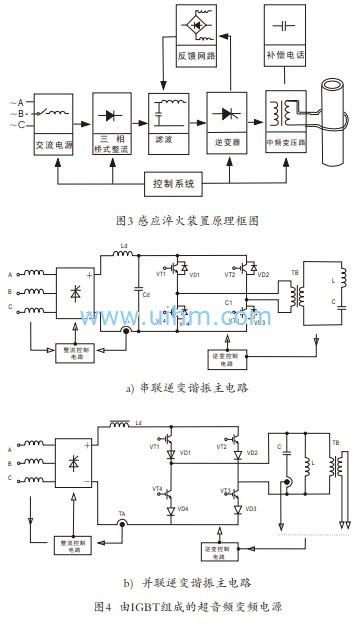
(1) variable frequency power supply block diagram, Figure 3 Figure 4.
(2) English IGBT stands for Insulated Gate Bipolar Transistor, insulated gate bipolar transistors. Traditional bipolar power transistor with high pressure, low pressure drop characteristics of conduction, switching speed is slow, and is not suitable for high-frequency applications; power MOSFET switching speed, but the breakdown voltage and current capacity small. IGBT combines high withstand voltage bipolar power transistors, turned on the pressure drop characteristics and power MOSFET switching speed characteristics, suitable for high power applications, power electronic devices, has become the most widely used power one of the electronic devices, IGBT induction heating variable frequency power supply applications, more and more common. Mainly occupy kW power installed capacity of of 10KHz ~ 60kHZ, a few hundred to more than a thousand. Figure 4 is an induction heating power supply of the two main lines.
The IGBT choice mainly in three aspects need to be considered: the rated voltage, rated current and switching speed. Selection of the IGBT, first according to the circuit switching device in the voltage and current stress, to determine the voltage and current capacity of the IGBT normal work needs. IGBT voltage control devices, is necessary to improve their driving and protection circuit. IGBT integrated driver chips more EXB series IGBT integrated driver IC production Fuji, for example, the EXB series chip is divided into a series of standards and high-speed series. The standard series chip IGBT switching frequency caps l0kHz, high-speed chip series IGBT maximum switching frequency to 40 kHz. Standard series of EXB850 EXB851, high-speed series EXB840 and EXB841.
Single-phase inverter power is generally suitable for the application of the range of several hundred watts to several kilowatts, while the three-phase inverter is generally suitable for dry within a few watts to hundreds of kilowatts, or even thousands of kilowatts range of applications. When the IGBT module is used to switch large capacity inverter current, sometimes the devices are used in parallel. The device used in parallel, it is important that the same amount of current through the devices are connected in parallel in the design to make. Once the current loss of balance, and possible damage to the device due to the current focus on flow through a single device.
(3) by the power field effect transistors (referred to as, the power MOSFET) as a high frequency power inverter switching tube of the main circuit shown in Figure 5 a). The advent of the power MOSFET, opened the door of the the power semiconductor high-frequency applications. The power MOSFET mainly used in voltage below 600V, power stem from hundreds of milliwatts to several watts of occasions.
Power MOSFET is still the fastest growing power devices to reduce the on-state resistance is still power MOSFET in the future research direction, for a long time is not much of a breakthrough. MOSFET second breakdown can be described as the most likely to use the power switching devices, it has been widely used in small and medium-sized power of low-voltage power supply, solid state switch, etc..
The current capacity of the power MOSFET is usually not very large, so flow through the occasion of a large current, and have a plurality of power MOSFETs used in parallel. Power MOSFET just superior parallel characteristics can directly parallel use of multiple devices, the current concentration of a particular device and cause damage to the device is its outstanding advantages, and will not appear in the parallel application. This is because the on-state resistance of the power MOSFET has a positive temperature coefficient, when a MOSFET's drain current increases due to the increase in conduction loss will lead to its junction temperature rise in the junction temperature rise resulting in on-state resistance is increased, the drain pole current will naturally be reduced. Therefore, the power MOSFET can be used in parallel to achieve the natural flow.
Power MOSFET is more suitable to be used in parallel, in actual use, in order to achieve satisfactory results, usually with some protective measures: such as, ① prevent the first gate - voltage source overvoltage protection. ② prevent excessive current load. ③ prevent overheating temperature is too high. (4) to prevent electrostatic breakdown, etc.. Since the power MOSFET has a certain input capacitance, it is easy to absorb the static charge, and the power MOSFET input impedance is high, it is difficult to bleed the charge and therefore is easy to cause electrostatic breakdown.
Power MOSFET power installed capacity in the commonly used integrated PWM control chip, such as the UC3525 Voltage PWM control chip; UC3842 current PW M control chip.
A high frequency power supply is shown in Figure 5 is composed of the inverter circuit (4) of the static induction transistor (SIT) b). Static induction transistor (SIT) and static induction thyristor (SITH) There are many similarities between the two structures and principles of high-frequency high-power electronic devices, electrostatic induction principle to control the operating current of the power switching devices. SIT and SITH has low power consumption, high switching speed, high input impedance, available gate voltage control switch advantages, there is a great advantage in the high frequency band for high-power induction heating power inverter device.
Static induction transistor (Static Induction Transistor) referred to the SIT, started to develop in the 1970s, development has now become a series of power electronic devices. It is a multi-conductive unipolar device has the advantages of high power output, high input impedance, switching characteristics, good thermal stability as well as the ability of anti-radiation. Now commercialized SIT can work in a few hundred kHz, the current up to 300A, voltage up to 2000V, has been widely used in high-frequency induction heating equipment (such as 200kHz 200kW high-frequency induction heating power supply).
The electrostatic induction thyristor (Static Induction THyristor) referred to as the SITH. It belongs to the bipolar switching devices, developed and produced since 1972, development has preliminarily mature, and some have already been commercialized. Compared with the GTO, SITH has many advantages, such as on-state resistance, lower-state pressure, fast switching speed, small loss, di / dt and du / dt higher tolerance existing product capacity has reached 1000A/2500V 2200A / the 450V, 400A/4500V, operating frequency is up to 100kHz. Also play an important role in the DC speed control system, high-frequency heating power supply and switching power supply and other fields, but the manufacturing process is complex, the high cost is an important factor to hinder its development.
3 (middle) frequency quenching transformer
1) The role and types of
Height (in) frequency quenching transformer is connected to the inverter power supply sensor - part system load, one of the essential key electrical components. The completion of the inverter power supply impedance and the sensor - Part system load impedance match, is isolated from the power supply and the heating load, the power transmission process of the voltage and current changes and other functions.
Height (in) frequency quenching transformers and transformer on the same principle, but the operating frequency, the structure has its unique place, generally water-cooled. Composition: a ferrite or iron core, the primary winding, secondary winding, the end portion of the wiring board, the frame and the water cooling system, etc.. The structural characteristics: IF early, the secondary winding has a certain turns ratio, primary Most single turn, 2 turns and the turns. Induction hardening using the air-core transformer, the transformer structure of the distribution of two concentric cylindrical-shaped coil, the primary coil
A monolayer, the secondary winding is a single turn. Rapid cooling coil through high-pressure water.
IF quenching transformer core quartet built by the silicon steel sheet shape around the hollow (middle pass water cooling) of copper coil. High frequency core select ferrite; high frequency optional permeable core, hollow frame directly around the coil.
2), the choice of IF quenching transformer turns ratio N
The high IF primary and secondary windings have a turns ratio, the secondary most single-turn, connected directly to the sensor. More types of sensors, and sensors - Part impedance changes, always and power supply impedance matching, general tone early secondary coil winding turns ratio N, the secondary is a single-turn primary winding in general less than 50 turns . Generally speaking, the turns ratio N is the greater, the greater the value of the inductance L, the greater the resistance, and vice versa. In addition, there is the grid frequency to reduce N value increased; sensor design unreasonable loss increases, N To reduce; the quenched parts too slender, N values decrease; cable between the power supply and the load length, the greater the resistance and the smaller the value of N; Part greater the permeability, the greater the resistance of parts, and the N value is reduced. Turns ratio N can only be determined in the equipment on-site commissioning process, difficult to accurately theoretical calculations.
3) quenching capacity of the transformer as a power supply rated power 3 to 5 times, with the power connection.
4 sensor design introduced
The quenching of the workpiece into the line sensor is a wide range, with the hardening of the workpiece vary significantly general theoretical calculation error is large, most of the result of trial and error based on experience. The quenching with sensors in order to effect quenching and the shape of the workpiece is similar. Listed below are several sensors for reference.
5 Conclusion
Factory heat treatment process containing quenching, tempering, annealing, induction heating devices can be higher quality of the process requirements, and therefore a wider application of the device. Discussion of broad-brush above, the IF main power circuit structure and induction hardening device engineering methods. And readers a discussion and exchanges in this regard.

